Bracket + rail strategy
The support system needs to suit panel type, substrate, loads, adjustment requirements and installation sequence. Final bracket, rail, anchors and centres must be confirmed and engineered for the selected project.
 Discuss a Project
Architectural Façades · Technical Design Guide
Serious façade work depends on geometry, joints, supports, interfaces, materials, finishes and project evidence being coordinated together. This guide shows how Apollo structures that technical conversation without pretending one generic wall detail suits every building.
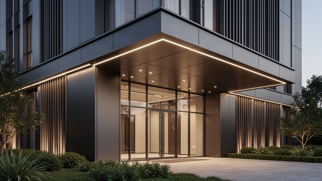
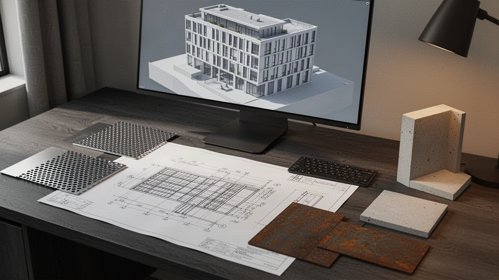
Architectural integration concept — illustrative only. Final panel build-up, support, drainage, lighting interfaces and certified performance depend on the selected system and project.
01 · Design inputs
Early concept drawings are useful. Detailed coordination becomes much stronger once the project team provides the structural, envelope and performance inputs that affect panelisation and fixing design.
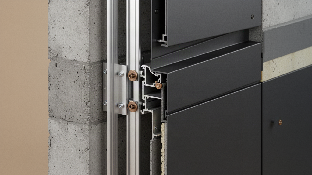
02 · Fixings, joints + interfaces
Support rails, brackets, anchors, panel returns, movement, drainage and adjacent construction determine whether the visual concept can become a coordinated system.
The support system needs to suit panel type, substrate, loads, adjustment requirements and installation sequence. Final bracket, rail, anchors and centres must be confirmed and engineered for the selected project.
Joint width, backing, drainage, movement and visual shadow lines are coordinated with panel geometry and the building-envelope strategy.
Folded returns, expressed joints, corner cassettes and trim pathways are developed to keep the façade geometry intentional at external and internal corners.
Window reveals, doors, soffits, parapets, penetrations and transitions to adjacent materials should be resolved before panel release.
03 · Forming + pattern development
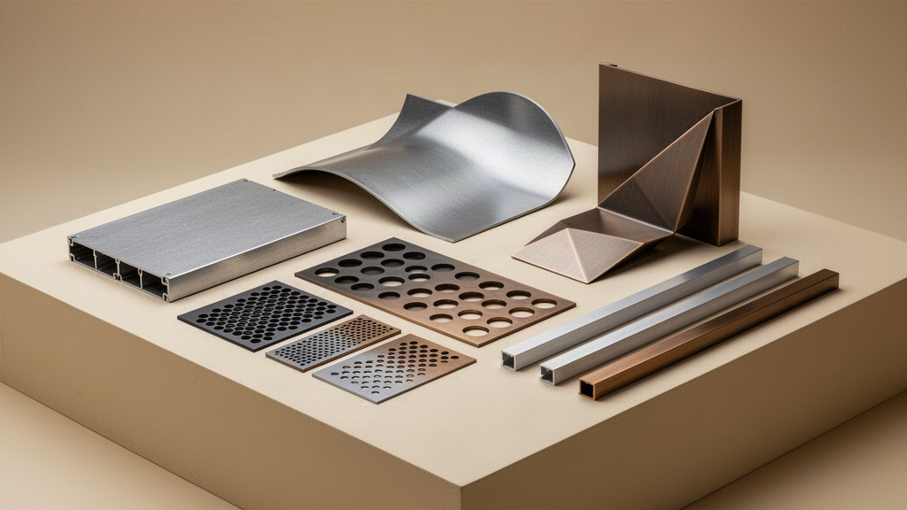
Folded geometry, curvature, perforation and linear fins all affect stiffness, framing, fabrication, packing and visual tolerances. They should be developed as architectural systems, not decorative overlays.
Panel geometry can move from simple cassettes through folded and faceted forms where fabrication, transport and structural behaviour support the design.
Curved or segmented surfaces require early coordination of radius, panel width, joint rhythm, support system and finish expectations.
Pattern, open area, edge distances, panel stiffness, solar control, ventilation and visual density should be reviewed together rather than as a graphic treatment alone.
Profile depth, spacing, orientation, support centres, thermal movement and fixing visibility drive the final linear façade system.
04 · Material-specific coordination
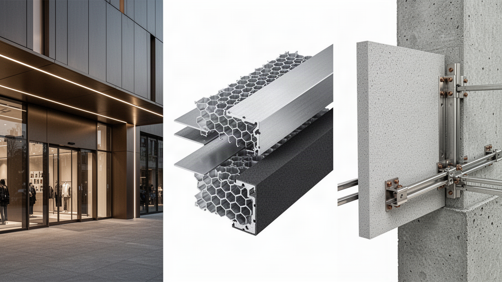
Large-format metal panels, bonded honeycomb construction and cementitious façade elements do not share the same detailing, handling or evidence requirements.
Wall-to-soffit transitions, access, drainage, lighting and service interfaces should be considered as part of one architectural surface package.
Face sheets, core, edge construction, bond evidence, fire performance, support spacing and panel handling are verified against the selected system.
Panel weight, anchors, reinforcement, lifting points, joints, tolerances, water management and structural / seismic requirements are project-specific design inputs.
05 · Drawings, samples + mock-ups
The exact drawing responsibility depends on the contract and manufacturing pathway. Apollo can coordinate the information flow so architectural intent, manufacturability and production release are not treated as separate conversations.
Architectural elevations, plans, sections, material intent, key dimensions and interface zones supplied by the project team.
Panel grids, module logic, joint locations, corner conditions, openings and repeated types developed for coordination.
Typical fixing concepts, panel returns, rail / support logic, interfaces and selected details progressed around the actual project.
Colour, gloss, texture, perforation or material samples can be aligned with the approved project direction before production.
Where appropriate, physical mock-ups can be used to review appearance, joints, interfaces and buildability before the full production run.
Final approved drawings, quantities, finishes, packaging requirements and controlled project information form the basis of manufacture.
06 · Evidence boundary
This is the rule that keeps the division credible while supplier qualification continues.
Apollo offers a project-led façade and surface-system pathway rather than a fixed commodity catalogue.
The division covers solid aluminium, perforated, laser-cut, fins / battens, honeycomb, mesh / expanded metal, weathering steel and UHPC / architectural concrete pathways.
Projects can be reviewed from architectural drawings, dimensions, material intent, site exposure and performance requirements.
Shop-drawing coordination, samples / mock-ups, fabrication QA, export packaging and supply can form part of the project pathway where applicable.
—Exact panel sizes, thicknesses, alloys, reinforcement and support centres
—Wind-load / deflection performance and structural calculations
—Fire classifications and complete wall-assembly compliance
—Coating system, finish warranty and coastal / salt-spray evidence
—UHPC / GFRC mix, reinforcement, anchors, weights and lifting details
—Maximum curved / folded geometry and manufacturing tolerances
—BIM / Revit deliverables available from the selected manufacturing pathway
—Named project references and third-party verification for completed work
Project review
Plans, elevations, sections, dimensions, material intent, site location and known performance requirements are enough to start a useful first review.