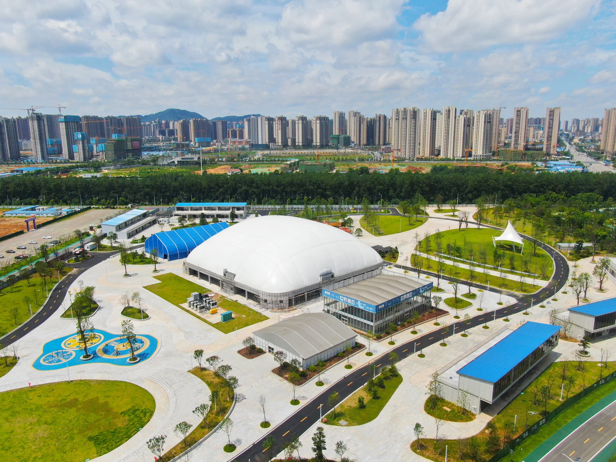
An air-supported sports facility should be briefed as a complete operating building system, not as a membrane placed over a court. The sport footprint, climate, air-support plant, entrances, anchoring, internal services, emergency planning and local project responsibilities need to be coordinated before the final dome geometry and supply package are developed.
Planning guidance — final supplied configuration remains project-specific.
01
Define the complete covered footprint
Start with the number and type of courts or activity zones, then add run-off, circulation, player and spectator space, equipment storage, entrances and any support areas that need to sit inside the enclosure.
Playing-line dimensions alone are not enough to define the dome footprint. Clear height and the position of lighting or other overhead equipment also need to suit the intended sports.
02
State the operating model
Record whether the enclosure is intended for seasonal use, a longer operating period or another project-specific programme, along with expected hours, occupancy, staffing and maintenance capability.
The operating model affects plant, access, energy use, maintenance planning and the way the facility is reviewed by the destination project team.
03
Provide site-specific climate criteria
Wind, snow where applicable, temperature range, heavy rain, exposure and other destination conditions should be defined before engineering is frozen. Generic climate assumptions should not be transferred between locations.
The project engineering and current manufacturer documentation should control final geometry, membrane specification, pressure strategy and operating limits.
04
Treat air support and backup as essential plant
An air-supported structure depends on a controlled internal-pressure system. Primary air-handling equipment, controls, monitoring and the required backup or redundancy pathway should therefore be treated as core facility infrastructure rather than optional accessories.
Final plant capacity, electrical requirements, standby strategy and operational procedures are confirmed for the actual project rather than inferred from another dome.
05
Coordinate anchoring, entrances and emergency egress
The perimeter anchoring or foundation interface must be designed for the actual ground, dome system and destination requirements. Local civil work should follow the approved project information.
Personnel entrances, larger equipment or vehicle access where needed, pressure-control arrangements and emergency egress should be laid out with occupancy, circulation and life-safety requirements in view.
06
Design lighting and environmental services with the dome
Sports lighting, heating or ventilation where required, controls, emergency systems and other services should be coordinated before the final internal layout is locked. Equipment positions should not conflict with play, clear height, membrane geometry or maintenance access.
Local electrical, mechanical, fire/life-safety and statutory design remain destination responsibilities unless a written project scope states otherwise.
07
Separate Apollo supply from local project work
Apollo coordinates the supplied air-dome product pathway and available project information. Foundations and civil work, local installation arrangements, utility connections, local engineering sign-off, permits and statutory compliance remain separately defined.
A strong project brief should therefore identify both the required supplied system and the local professionals or contractors responsible for the site-specific work.