01 · HLJÓÐ LED technical diagram
Outdoor Aluminium LED — Cabinet Anatomy
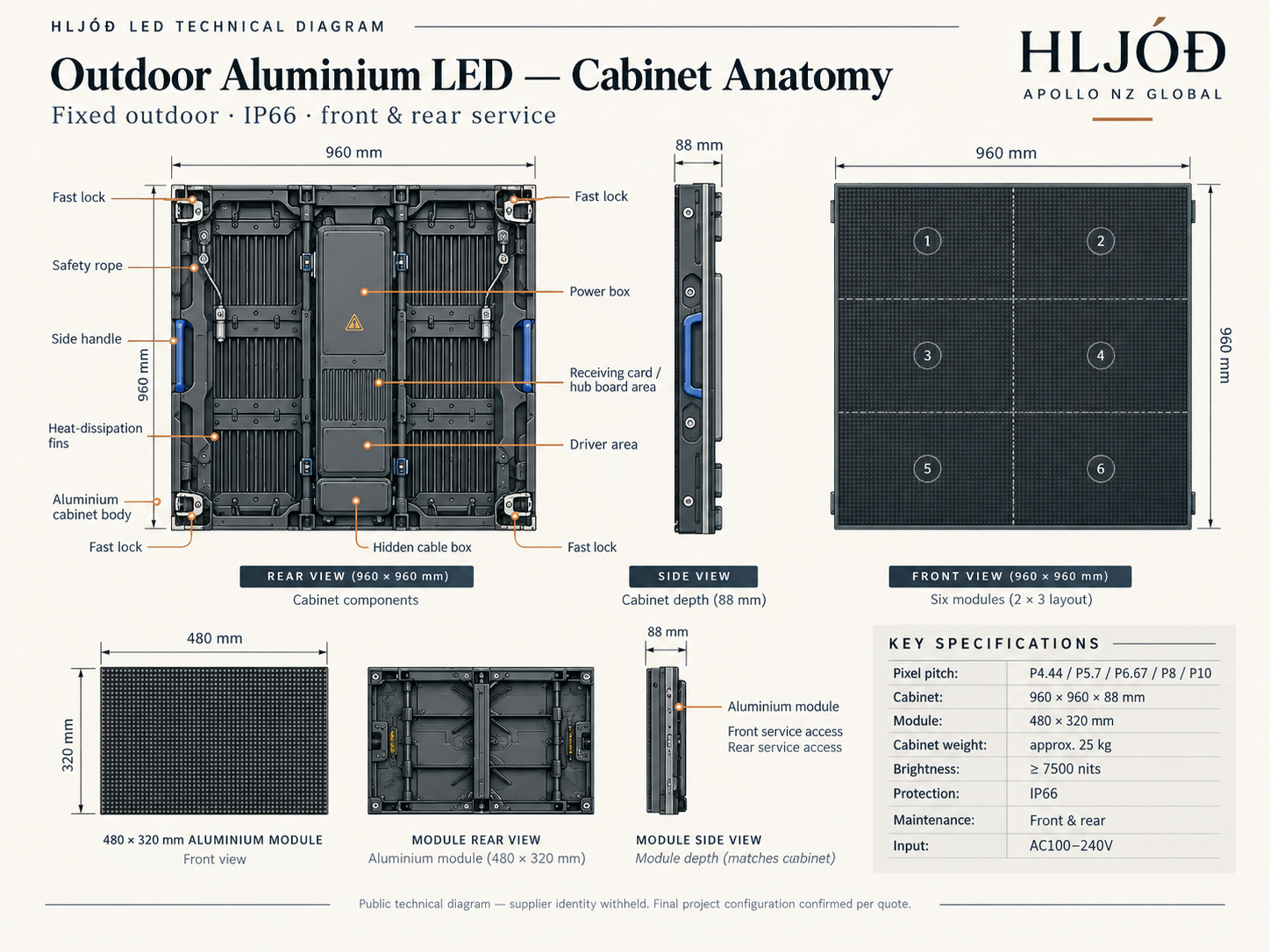
960 × 960 × 88 mm cabinet anatomy, six-module layout and public-facing component callouts.
 Start LED Project
HLJÓÐ · Technical Diagrams
Approved public-facing diagrams for system understanding, specification discussions, project coordination and tender support. Final engineering and manufacturer-approved configuration remain project-specific.
These diagrams are technical planning assets. Where a sheet is labelled conceptual or project-specific, it must not be used as an approved-for-construction detail.
960 × 960 × 88 mm cabinet anatomy, six-module layout and public-facing component callouts.
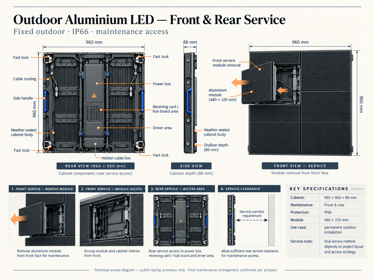
Front-module removal, rear-access components and project-specific service-clearance pathway.
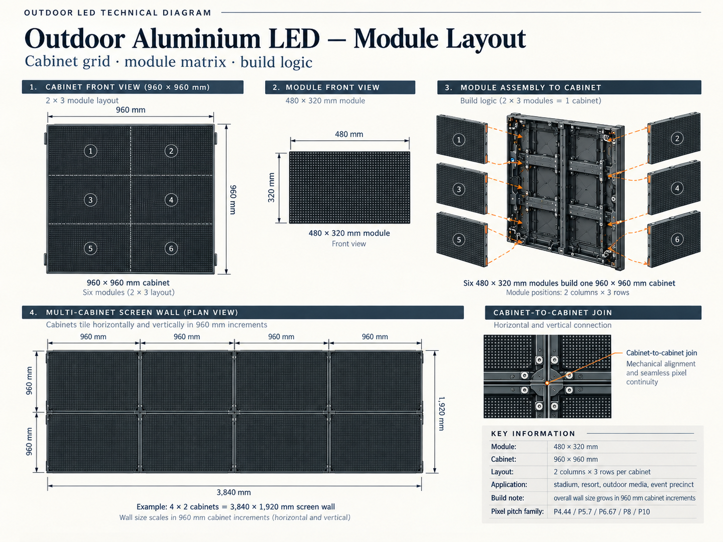
480 × 320 mm module, 2 × 3 module matrix, 960 mm cabinet and multi-cabinet screen-wall build logic.
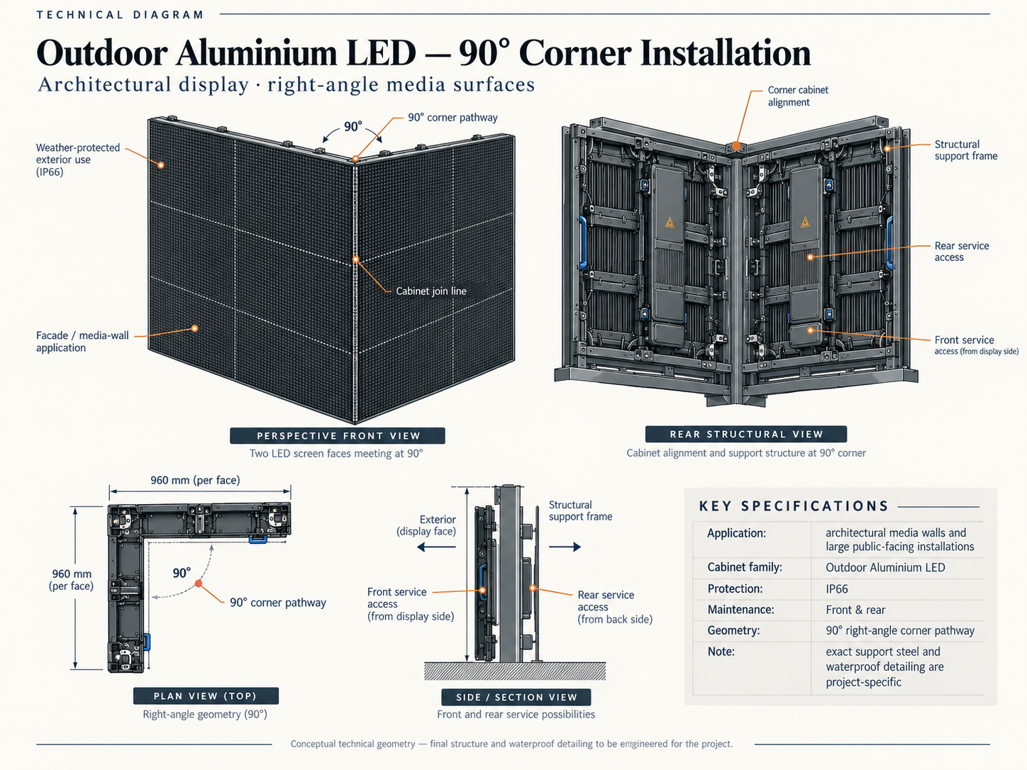
Conceptual right-angle media-wall geometry with cabinet join, support and service interfaces.
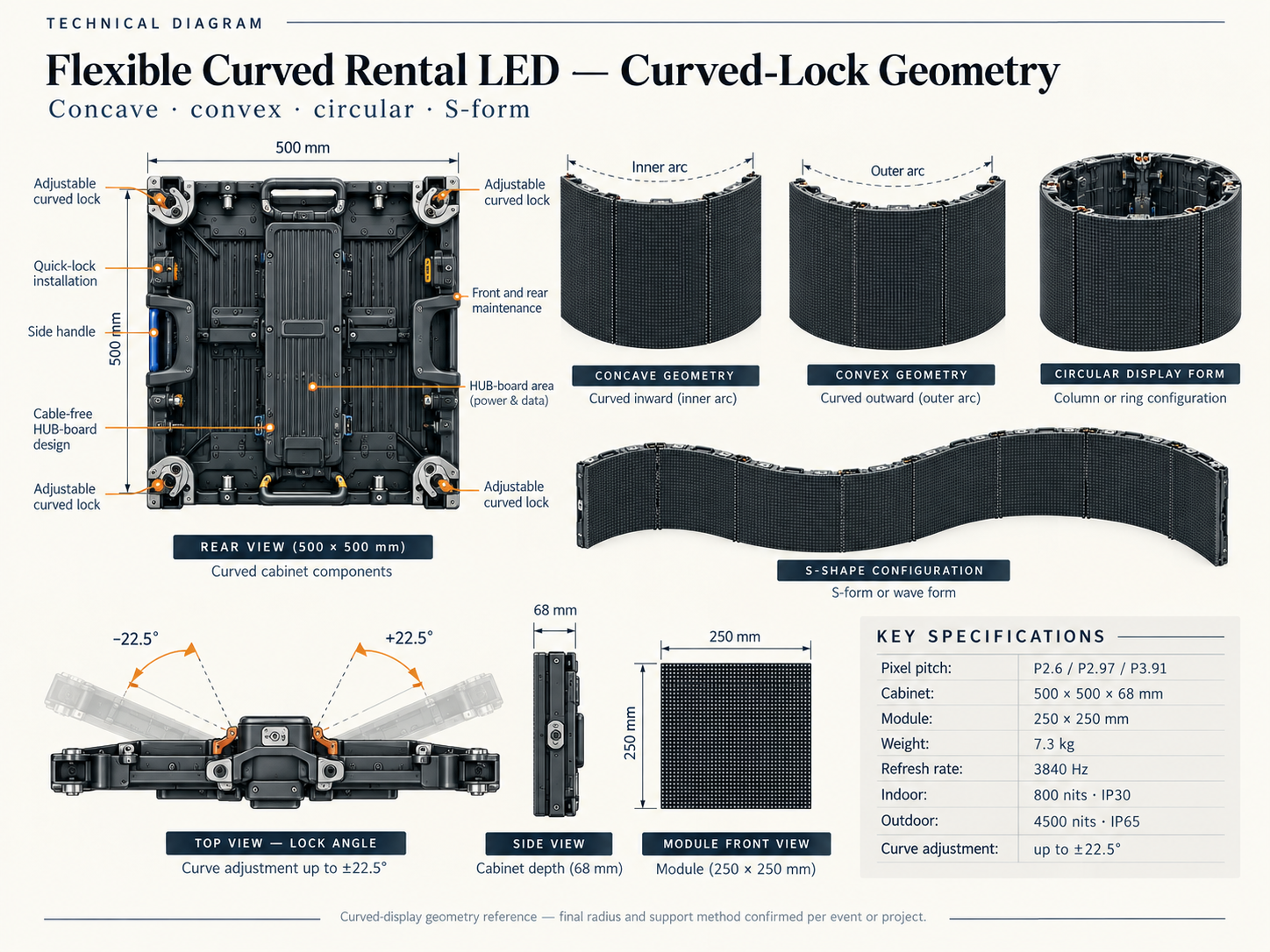
Concave, convex, circular and S-form display geometry using the 500 × 500 × 68 mm flexible cabinet pathway.
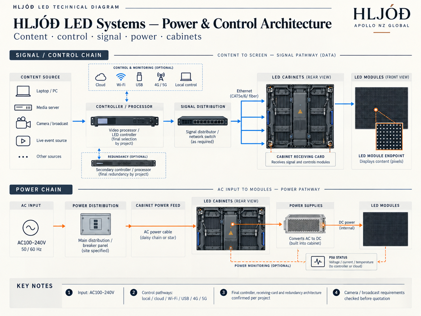
Generic project architecture for content sources, processor, signal distribution, receiving cards, cabinet power and optional monitoring.
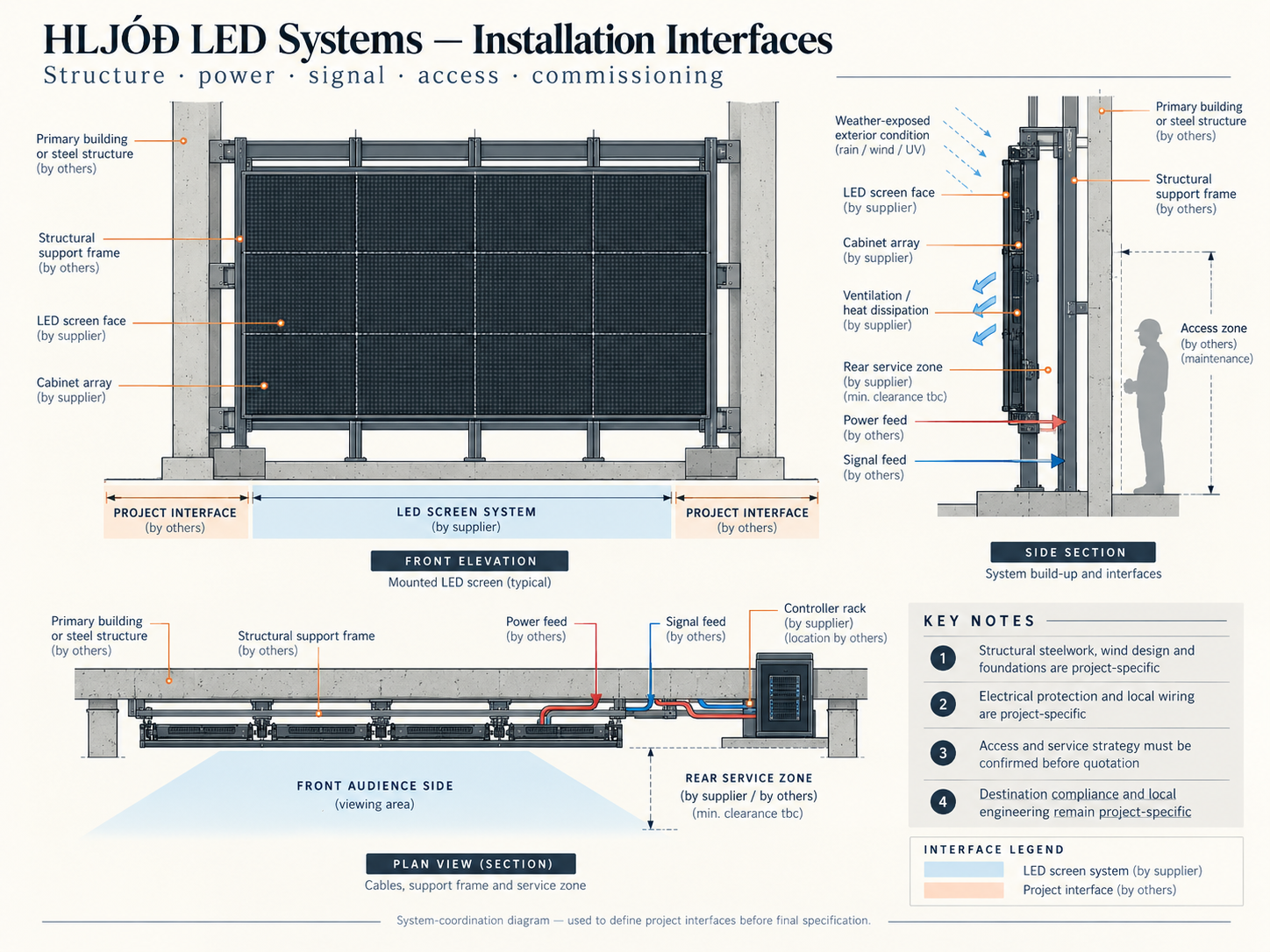
System-coordination diagram covering LED screen, support structure, building interface, power, signal, access and commissioning boundaries.
Use these diagrams in context
Start with the relevant product-family technical data sheet, then use the Smart LED Project Brief to turn the platform into a project-specific cabinet matrix, power, installation and delivery brief.